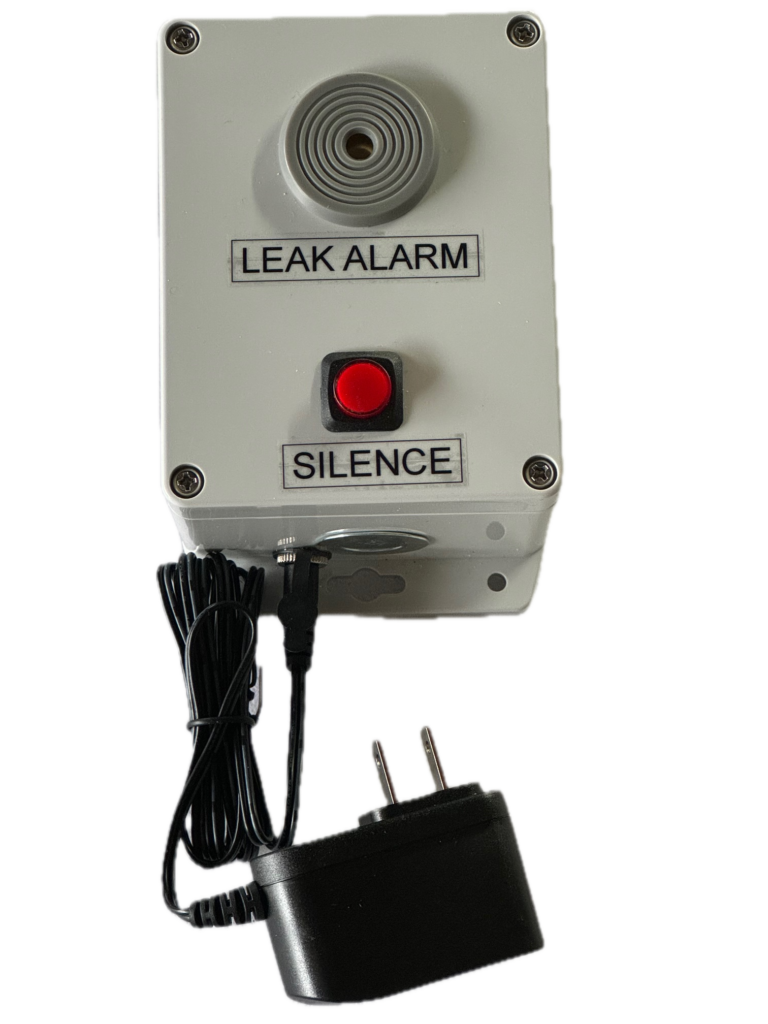
TRM Wall Alarm replaces the obsolete TRM Remote Alarm Type-RO and adds a new direct monitoring capability.
Function 1 – Classic Remote Alarm. An audible/visual alarm that can be mounted next to the control panel or in a remote location. Power and switching come from the control panel.
Function 2 – Direct Sensor Monitoring. Monitor up to four TRM-ALOS “Any Liquid” Optical Sensors or up to four TRM-DFS-3 indoor “fuel only” sensors. No control panel or smart relay required.
In Remote Alarm mode, the TRM Wall Alarm can be wired in the same configuration as the older Type-RO devices where an alarm relay in a control cabinet supplies and switches either 12 Vdc or 24 Vdc through a normally open contact. In this configuration, the Wall Alarm simply turns on whenever 12 Vdc or 24 Vdc appears at its power connection terminals. The red LED in the SILENCE button is illuminated. The buzzer turns on. Two sets of SPDT relay contacts change state to switch on rotating beacons, loud horns or to signal other monitoring equipment. Pushing the SILENCE button silences the local buzzer, but the LED and the two alarm relays stay latched in their alarm mode until the underlying issue is corrected.
In the new Direct Sensor Monitoring mode, from one to four of the TRM-ALOS any liquid optical probes or from one to four TRM-DFS-3 indoor fuel-only sensors can be directly connected to the Wall Alarm without the need for a TRM-Easy5-Relay or Panel. When a leak is detected by one of the sensors the red LED switches on, the local buzzer switches on and the two alarm relays flip to their alarm state. Pushing SILENCE, stops the local buzzer but the red LED and the two relays stay latched in their alarm state until the underlying issue is corrected. When operated in the Direct Monitoring mode, only one type of sensor (either ALOS or DFS-3) can be connected to the TRM Wall Alarm.
There are two separate and independent SPDT (Form-C) relays. Each provides Normally Open, Normally Closed and a Common contact that change state when a leak is detected. One of the relays is normally energized which means the relay changes state when power is lost so that facility monitoring equipment can also detect power outage at the TRM Wall Alarm. A mix of TRM-ALSO and TRM-DFS-3 on the same circuit will not work.
The TRM-Wall-Alarm comes with a plug-in 5 Vdc supply so that it is ready to operate directly out-of-the-box as an alarm device for TRM-ALOS or TRM-DFS-3 stand alone applications. But in many cases it’s more appropriate to supply power from a nearby control panels and the TRM-Wall-Alarm will operate on either 12 Vdc or 24 Vdc (no need to specify in advance or set the input voltage at installation.)
TRM-Wall -Alarm has a built-in push-to-test capability. A short push triggers the red LED and buzzer; a longer, 3 second push will activate the output relays as well.
A pre-drilled 1/2″ conduit knockout with a hole plug is provided. Standard Accessories include a cable gland with a two hole grommet and the option-use 5 Vdc plug in supply.
Optional Accessories include a low cost 120/240 Vac -to- 12 Vdc / 10W DIN rail power supply; a DIN rail mounted DC/DC isolator (needed only if monitoring DFS-3 sensor and the panel supply is grounded) ; DIN rail expansion relay if the the built-in Form-C relays do not provide enough external contacts.
Key Features
Enclosure :
White polycarbonate. Approx 3.5″ wide x 4.5″ high (90 mm x 115 mm) with mounting flange
Operating Voltage:
5/12/24 Vdc either switched by monitoring panel for Remote Alarm Mode or controlled within the Wall Alarm by sensors for Direct Monitoring Mode. The Wall Alarm operates on any of these voltages. There are no jumpers, switches or pre-order selection requirements.
Operation Mode Selection:
Occurs automatically based on wiring. No jumpers or switches to set.
Buzzer:
95 db at 30 cm
Silence Button:
LED illuminated pushbutton (red) Button LED stays illuminates as long as the leak detection sensor or control panel signal is active.
Relay Outputs:
Contact Rating: 30 Vdc / 250 Vac / 5 A.
2 x SPDT (Form C)
One relay is normally energized to remotely detect loss of power and one relay is not-normally energized. Both relays change state when a leak is detected and remained latched in alarm state until source of alarm is cleared.
Maximum Operating Temperature:
~70C

