TRM-DFS-3 System Design Ideas
Already have a Building Management System or similar security system?
If you want to add one or two fuel sensors to your pre-existing monitoring system, then TRM-DFS-3 is an excellent choice.
The TRM-DFS-3 is similar to an off-on switch that is never completely on or completely off… but most logic or digital inputs get by with less than perfect dry contact inputs. When a TRM-DFS-3 is in its “normal” state its resistance is less than 100 ohms and almost all monitoring systems will recognize this resistance as a “closed contact”. When the sensor detects diesel fuel (or gasoline or jet fuel), the sensor resistance climbs to over 1 meg-ohm in less than 10 seconds. All BMS type systems will recognize this as a “open contact” .
So… if you have a BMS or similar monitoring capability and you have a spare input for each TRM-DFS-3, you can connect the sensors directly to the BMS panel as if they are “Normally Closed Contact that Opens on Alarm”. That’s it! No adapters, no smart relay. The only accessory we recommend is a TRM-DFDS-3-SSHD to hold the sensor in place anywhere that is subject to foot traffic.
The only design rules are: Use an input that can monitor a switch type input; only one sensor per input; program the BMS to look for a closed contact that opens on alarm.
Have more than one generator or limited inputs?
If you want to add multiple sensors, use the TRM-Easy5-Relay-U to monitor up to 20 DFS-3 sensors.
Larger installations, particularly when there is more than one generator may require multiple sensors. For instance sensor can be used to monitor the floor under day tanks, quickly detect a leaking filter canister, find leaks at pump and valve manifolds or at flex couplings. In these situations, it often makes sense to compress multiple sensors into one or two BMS inputs.
The TRM-Easy5-Relay-U or the TRM-Easy5-SDR is made for these multiple sensor installations. The TRM-Easy5-Relay-U is a UL approved “smart relay” manufactured by Eaton Corporation and programmed by TRM Sensors. The TRM-Easy5-SDR is the same “smart relay” but with an added status screen.
Either version of the really can monitor up to 20 TRM-DFS-3 sensor arranged in two loops of 1 to 10 sensors per loop. For instance if you had a 2 generator installation and wanted to monitor under a shared day tank, at the pump pad, at a valve manifold and below fuel filters and flex couplings at each generator, you might allocate three sensors for the tank, valve and pump manifold on Loop#1 and the four additional sensors for the couplings and filters at the two generators.
The basic design rules are: Connect up to 1o sensors per loop. Each loop provides a dry contact alarm signal to connect to the BMS system. And there is s separate “any leak” summary contact that can be used to control a local or remote audible alarm if desired.
To operated the TRM-Easy5-Relay-U or the TRM-Easy5-SDR, your installation needs to provide 12 Vdc or 24 Vdc and about 4″ or DIN rail. Ideally, the relays should be installed in a protective pre-existing instrument enclosure. If you do not have a 12/24 Vdc supply or space in a nearby control cabinet…you might want to take a look at the next option.
No BMS … No Problem
In many facilities, there may not be a nearby control cabinet with space or perhaps there is no BMS
In many installations a free standing Leak Detection panel will make sense. The TRM-Easy5-Panel is available in two versions. One featured the TRM-Easy5-Relay-U while the other uses the TRM-Easy5-SDR and includes a small color coded display screen on the face of the relay
Both panels are 12″ x 12″ x 6″ NEMA-1 steel enclosures. They are designed to be mounted on an indoor wall surface. The panel is fabricated by a UL508 certified panels shop and is delivered as a UL508A certified industrial control panel. There is an internal DC power supply. The installer will connect 120 /240 Vac to the panel’s fused line voltage terminals. The panel is not pre-drilled so that conduit entries can be planned from top, side or bottom depending on what makes the best arrangement for your installation.
There are field wiring terminals for sensor loops and all output relays. Relay 1 and Relay 2 are normally open contacts that close if a fuel leak is detected on their respective sensor loops. relay 4 is a “common alarm” relay that closes on any leak detection and is typically used to operate a TRM Remote Alarm Type-RO. The Remote Alarm can be mounted anywhere with 500 feet of the Panel and there are internal daisy chain contacts if it makes sense to have a local audible alarm and another in a remote facility office.
The wiring diagram shown in the lower right corner is an example of the TRM-Easy5-Relay-U set up to monitor a total of 7 TRM-DFS-3 sensors. The same wiring diagram would apply to the TRM-Easy5-Panel, except that the supply voltage would be the 120/240 Vac line voltage supply.
Although this example shows the TRM-Easy5-Relay used for TRM-DFS-3 indoor diesel fuel sensors, the panel has several pre-programmed operating modes that are selected via jumpers (Relay-U) or via a set-up menu (SDR version). Other capabilities include combination Fuel and Coolant Leak detection, Outdoor Sump Monitoring, UST Monitoring, Hydraulic Oil Leak Detection, Elevator Pit Monitoring and sensor cable monitoring.
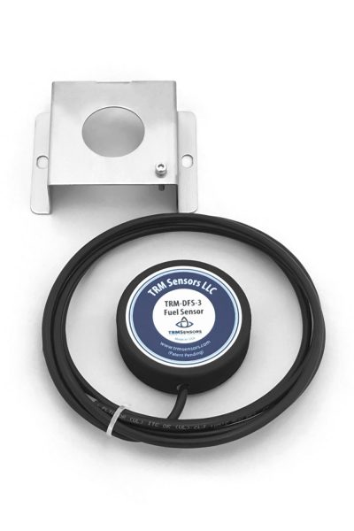
TRM-DFS-3 Sensor with TRM-DFS-3-SSHD stainless steel hold down
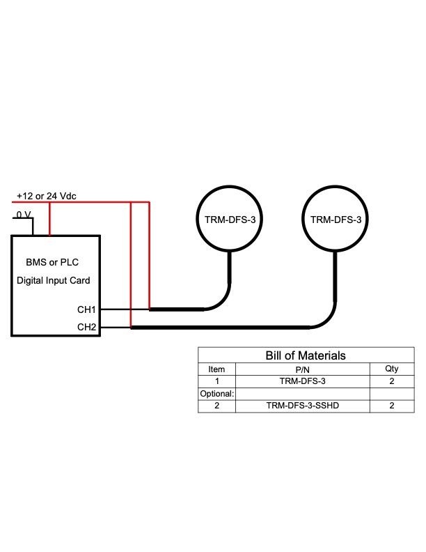
Two TRM-DFS-3 Sensors connected to separate BMS inputs
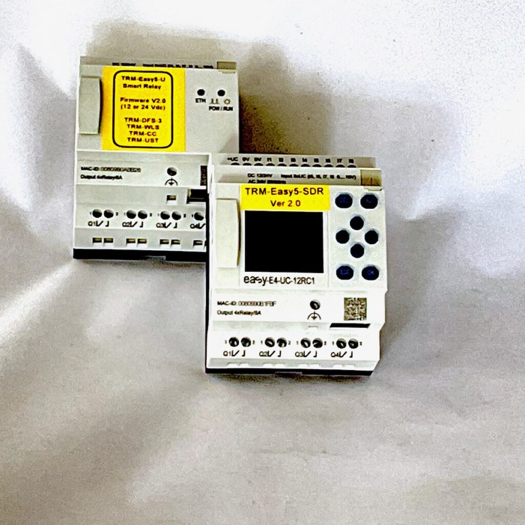
TRM-Easy5-Relay-U )left and TRM-Easy5-SDR
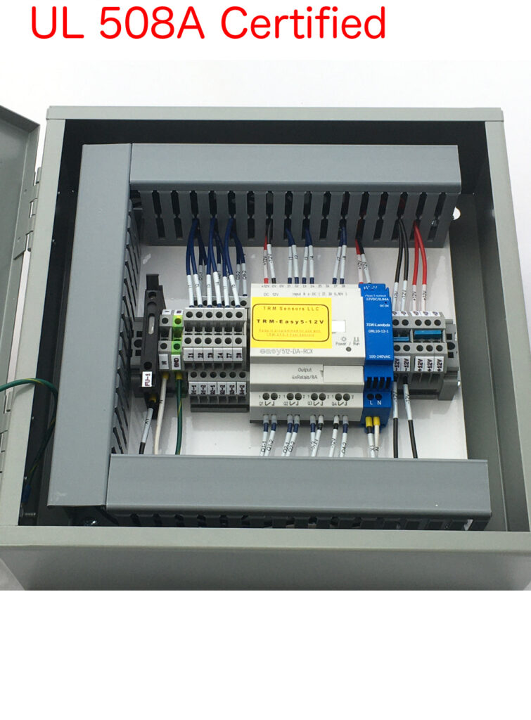
TRM-Easy5-Panel-Relay-U (SDR version is also available)
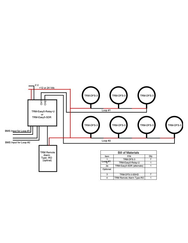
7 TRM-DFS-3 Sensors in two loops and monitored by TRM-Easy5-Relay
